Author Archives: chris - Page 9

Aft fuselage sides

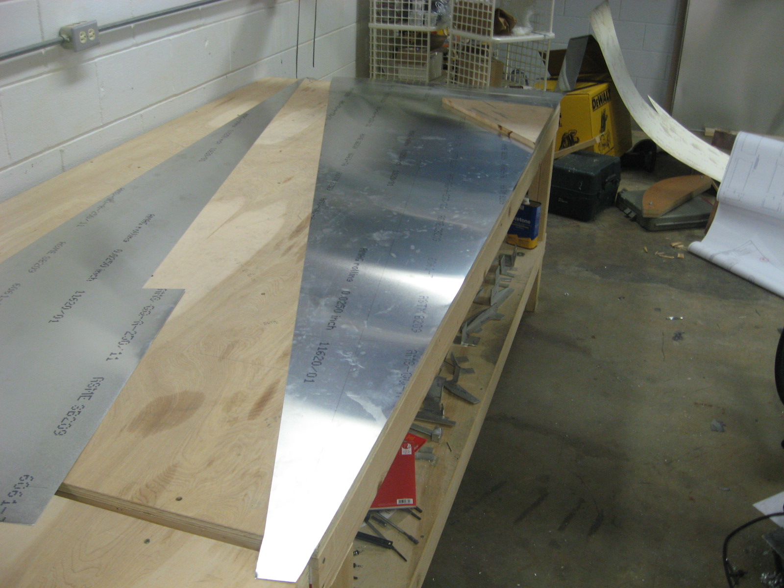
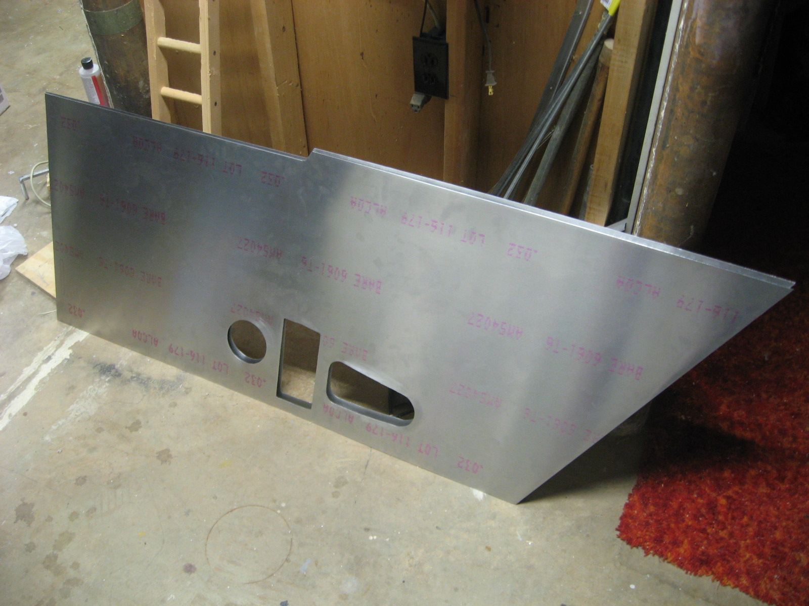
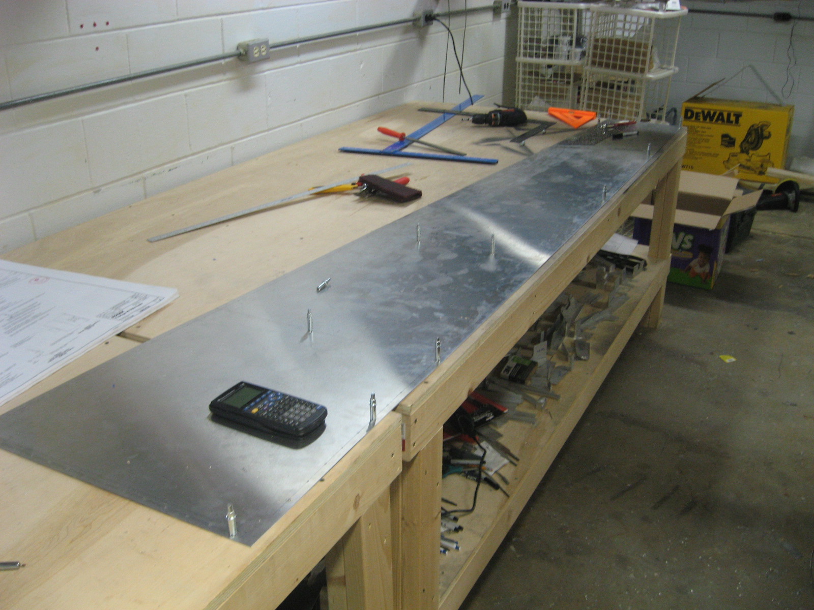
Cut the fuselage sides from sheet metal using the edge of a sheet as a straightedge.  I drilled all the holes with the two sides clecoed to each other and the table.

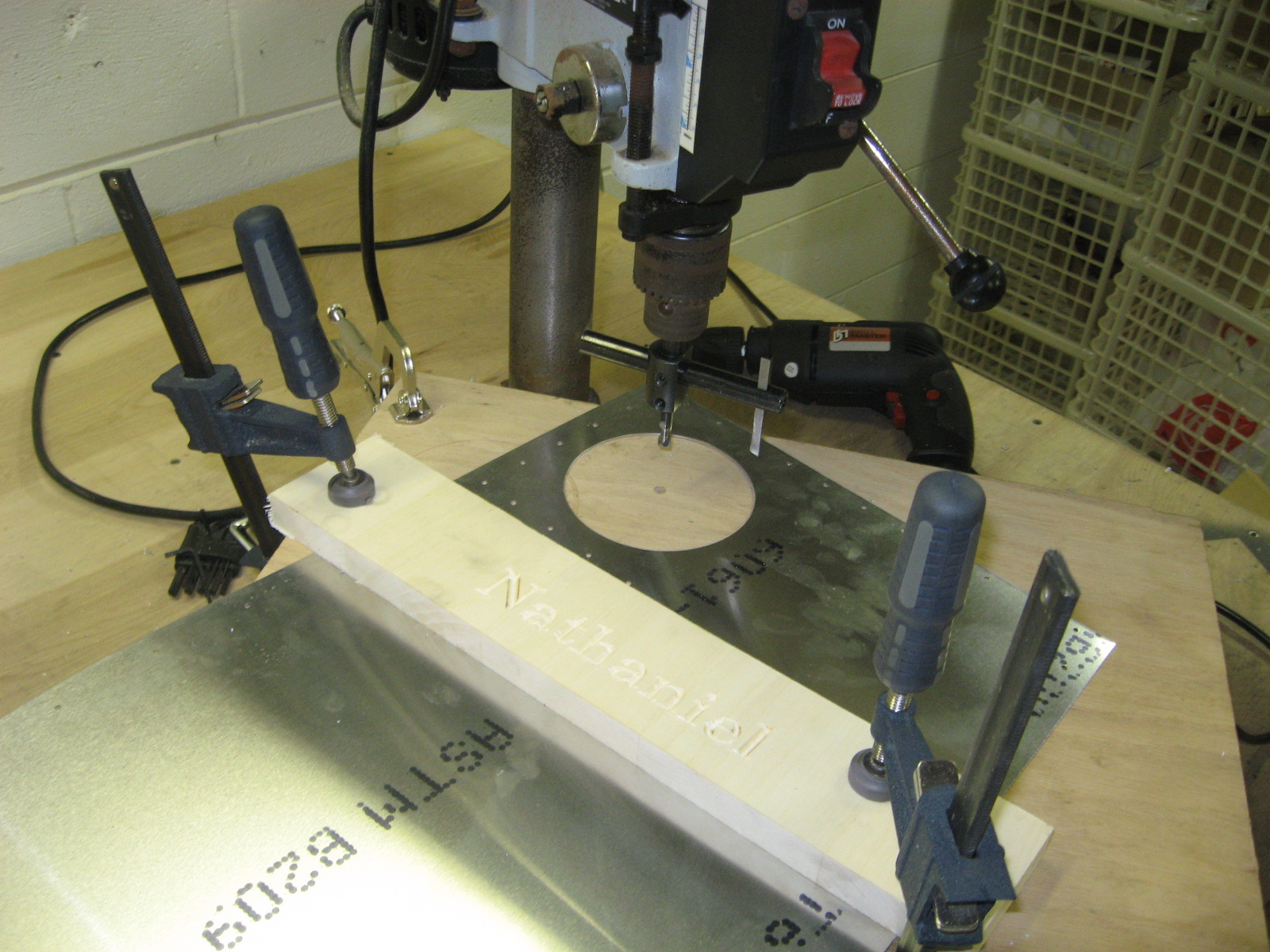
Cut the inspection holes with the fly cutter on my drill press.  I was pretty careful to get everything clamped down well.  The fly cutter occasionally stalls, but I found that if I raise the cutter up and down slightly while cutting, it gives the cutter a chance to return to speed before cutting again.  This seemed to help and it never stalled again.

I also started cutting the longerons.  These are simple cuts, just on really long pieces.

More fuselage parts

I had been concerned about laying out perfectly straight edges for the bottom of the fuselage, but then I realized I have a 12″ straight-edge in the form of left over .032″ sheet.

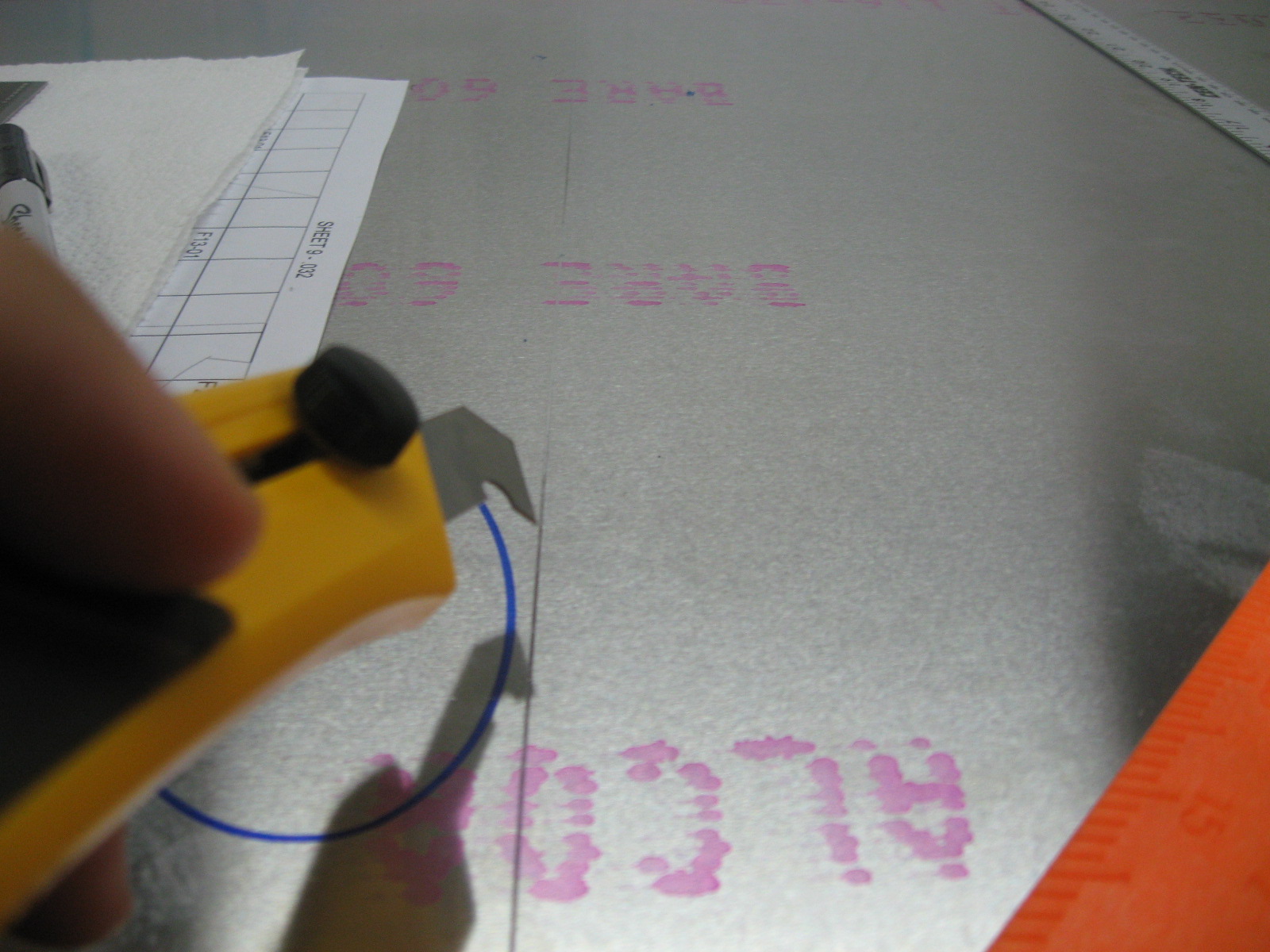
I used it to guide the olfa knife for about 3-4 passes.  Then since I am paranoid about having a nice, clean break on such a major part, I did several more passes for good measure.  There was plenty of room on the sides to cut out blanks for many of the Z channel pieces.  Unfortunately I keep confusing .025 and .032 parts and cutting blanks out of the wrong size aluminum.  It seems like I will still have plenty of material left over.

Here is the fuselage bottom lined up with the edge of my work table.

Fuselage parts

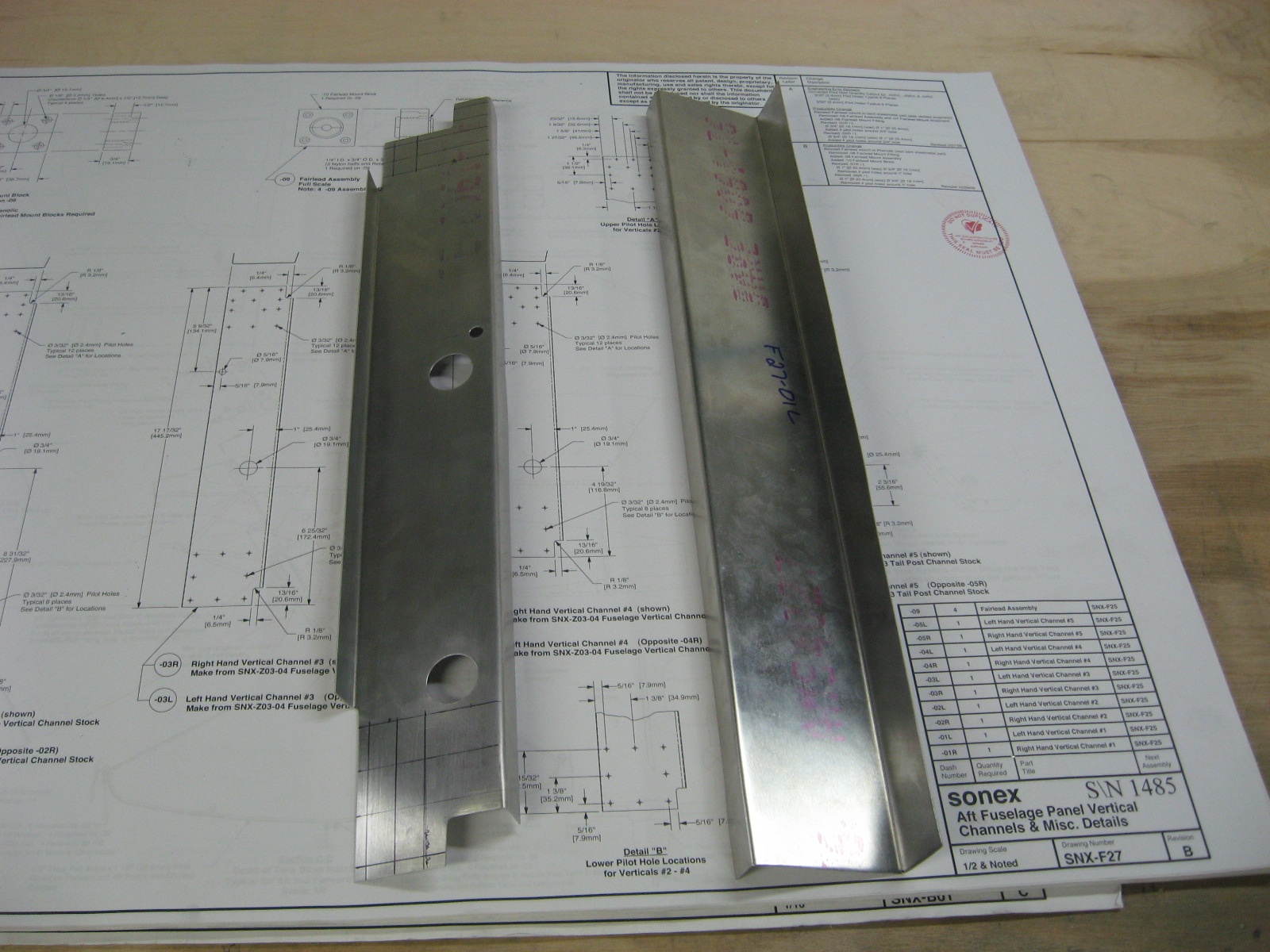
I bought a 30″ Harbor Freight brake and have been using to make the .032″ channel parts for the fuselage.  I’m planning on building a 8′ brake for the longer bends, but I am kindof wishing I had got the 36″ brake for a few slightly longer parts.  The brake also doesn’t seem to bend quite far enough to make a true 90 degree bend due to spring back, so I end up having to add a wooden block after the initial bend to get it the rest of the way.

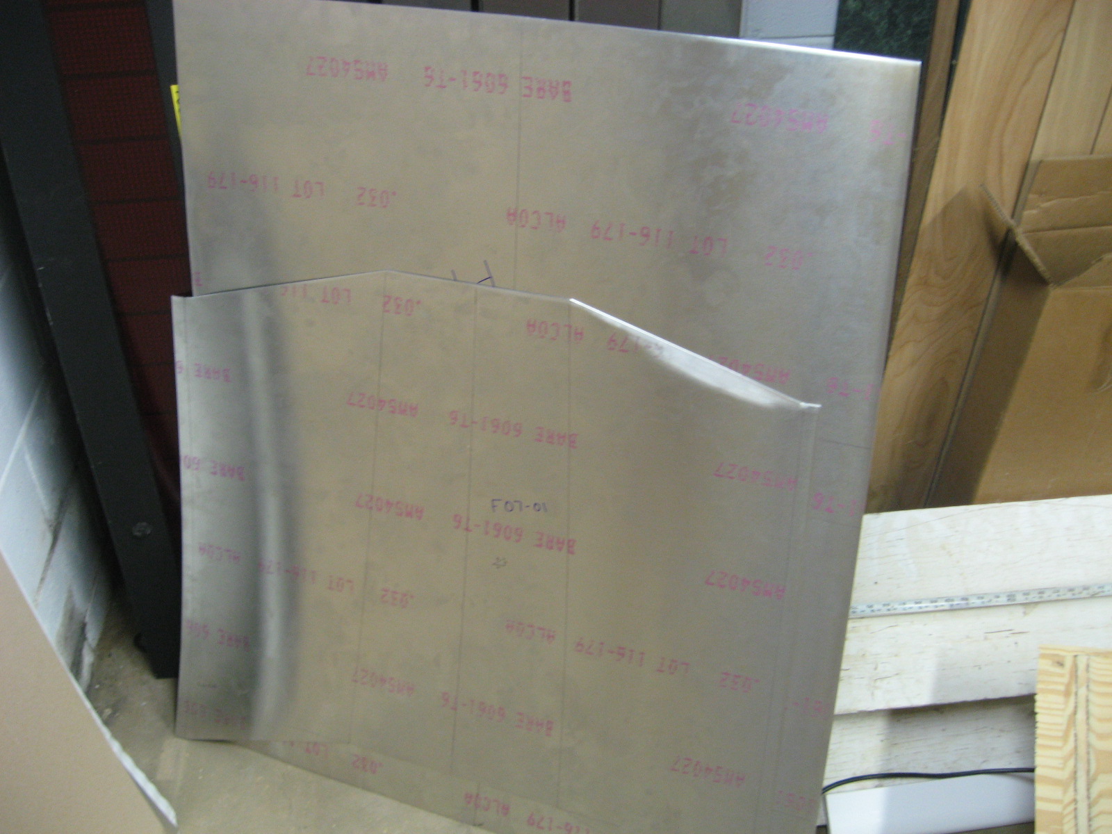
I have also cut some more larger pieces of .032″ sheet metal–the cockpit floor and the glare shield.

Starting on the fuselage

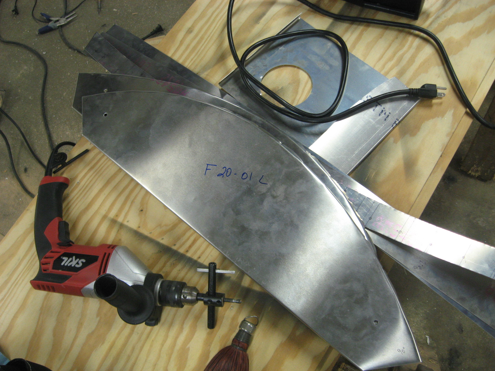
Started cutting sheet metal parts for the fuselage.  Here are the sides of the forward fuselage.  I ended up using a nibbler to cut the holes.

I used an Olfa P800 laminate cutter to score the cut lines.  I was able to snap the parts out right on the lines.

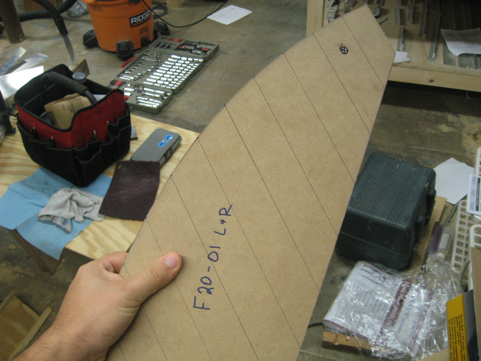
Here is a form block I made.

On top are the parts I formed with the form block and underneath are a few parts I cut out along with some scrap I practiced using the hole cutter on with a hand drill.  I decided not to try this on the fuselage sides and ended up using the slower and safer nibbler method.

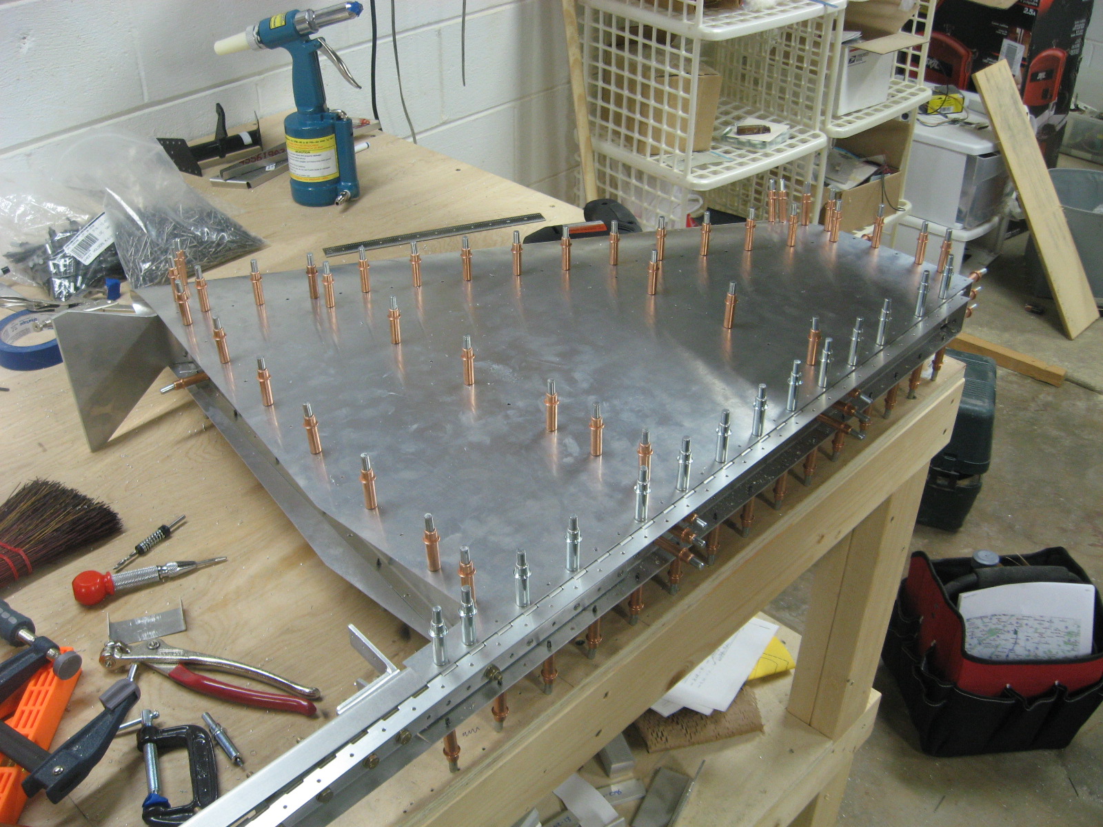
Horizontal Stabilizer Skinned

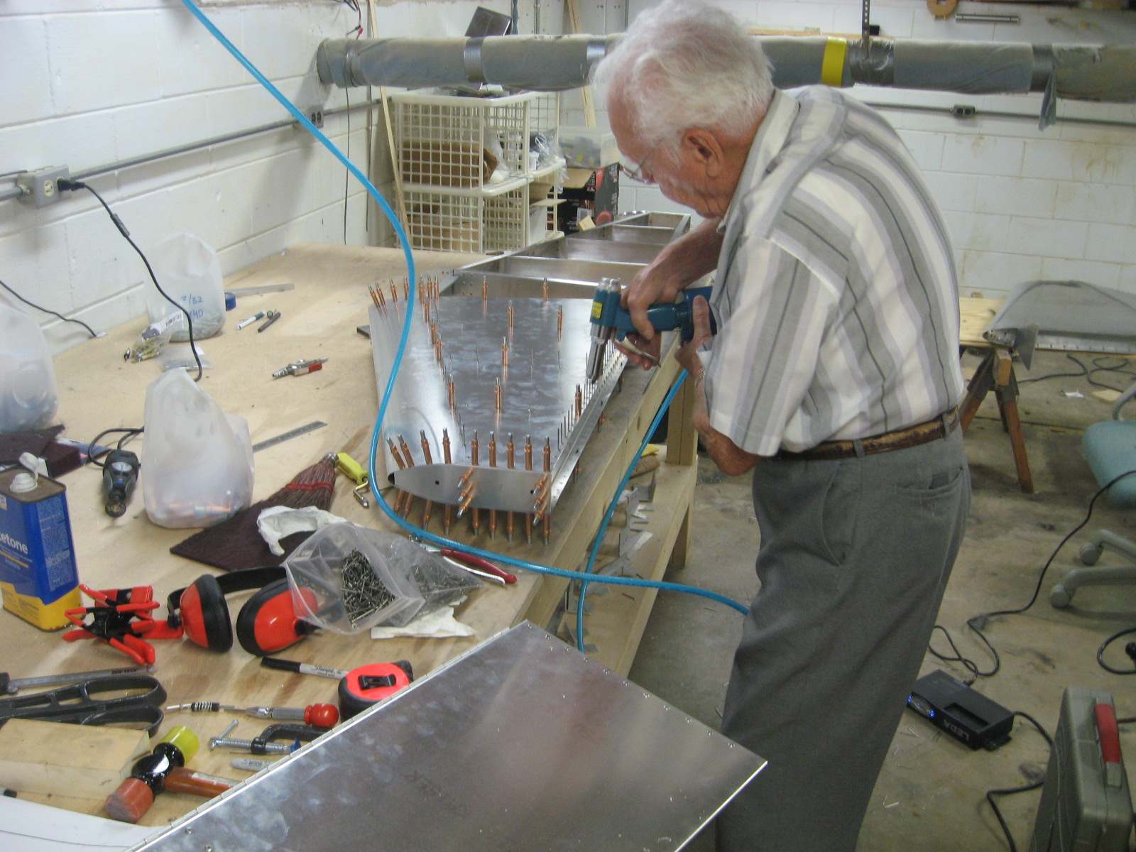
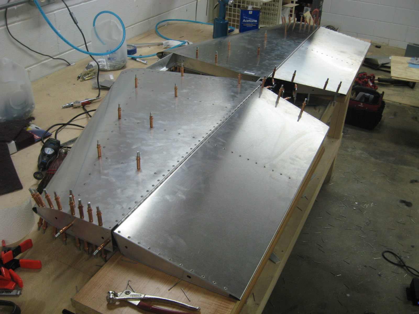
I thought it would be fun to have my friend Archie help rivet the stabilizer skins.  I got all the holes deburred and ready for riveting and had him come over one evening.  He ended up riveting most of the right stabilizer.  We had a good time with him telling some of his experiences aboard the USS Dunlap during WWII.

Attaching the hinges to the elevators and stabilizers and getting everything to line up seemed scary, but I was careful and everything worked out as perfectly as I could hope for.  Having it assembled and laid out on my 4’x8′ workbench really gives me an appreciation for how big this is (even if it is a small plane).

Horizontal Stabilizer Skinning


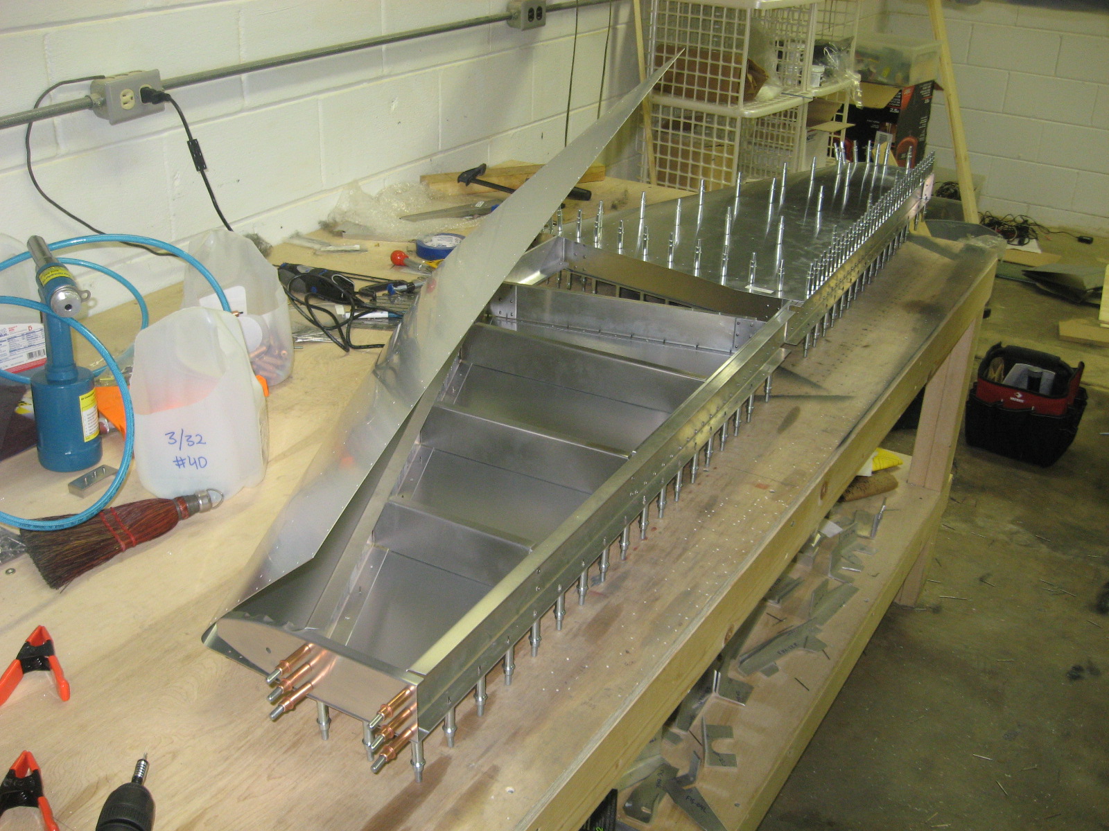
I started skinning the horizontal stabilizer.  Turns out I didn’t pay attention to what side was “up” and drilled all the holes for one side and had it clecoed on.  The next day I was thinking about it and realized I had a 50/50 chance of having it backwards.  Fortunately I got lucky.  Since both skins were laser cut, I THINK I could have simply switched them around and all the holes would have lined up, but I am very glad I didn’t have to.

It is a great feeling seeing the skin line up with all the ribs that were previously laid out.


Vertical Stabilizer riveted

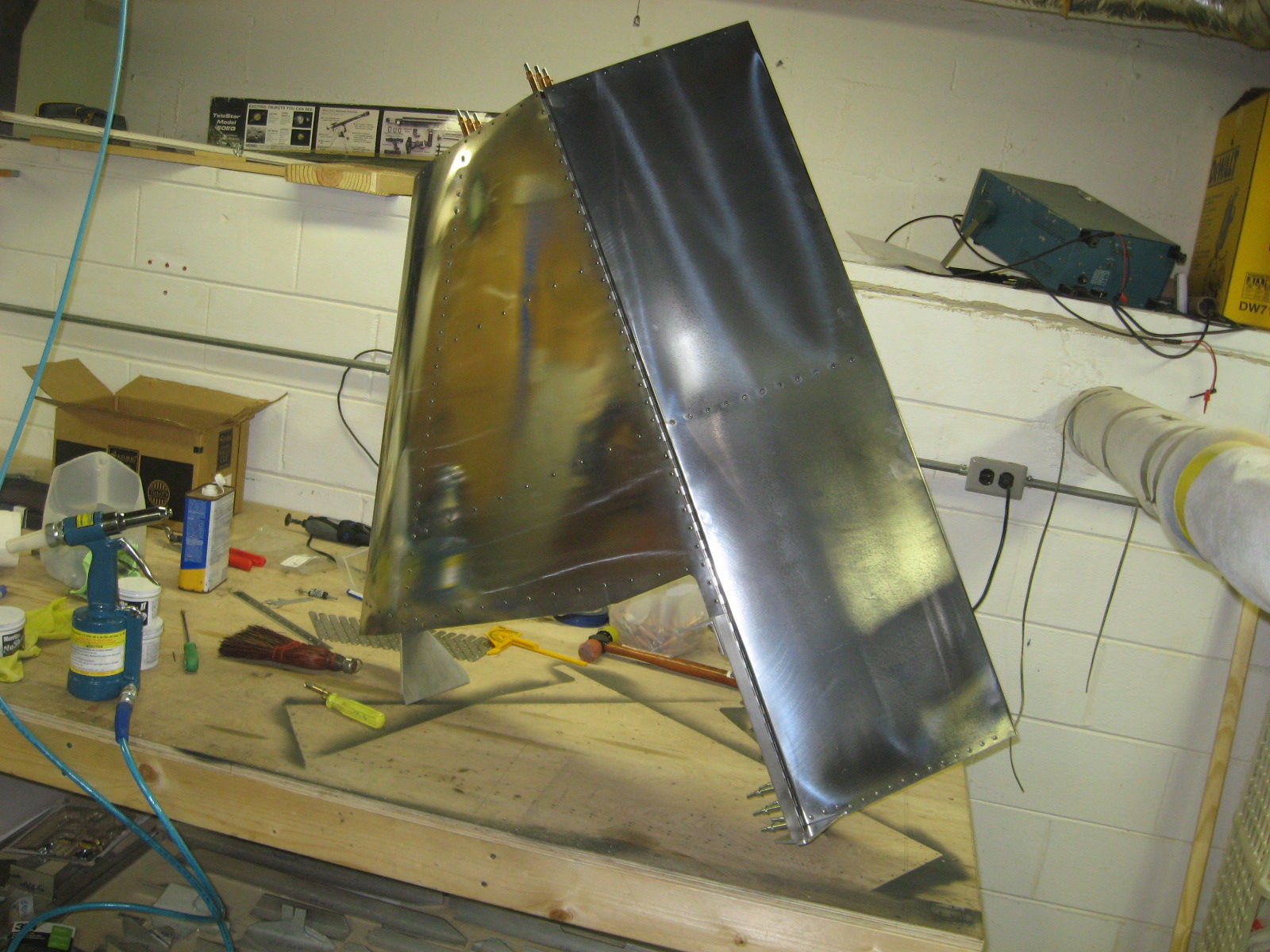
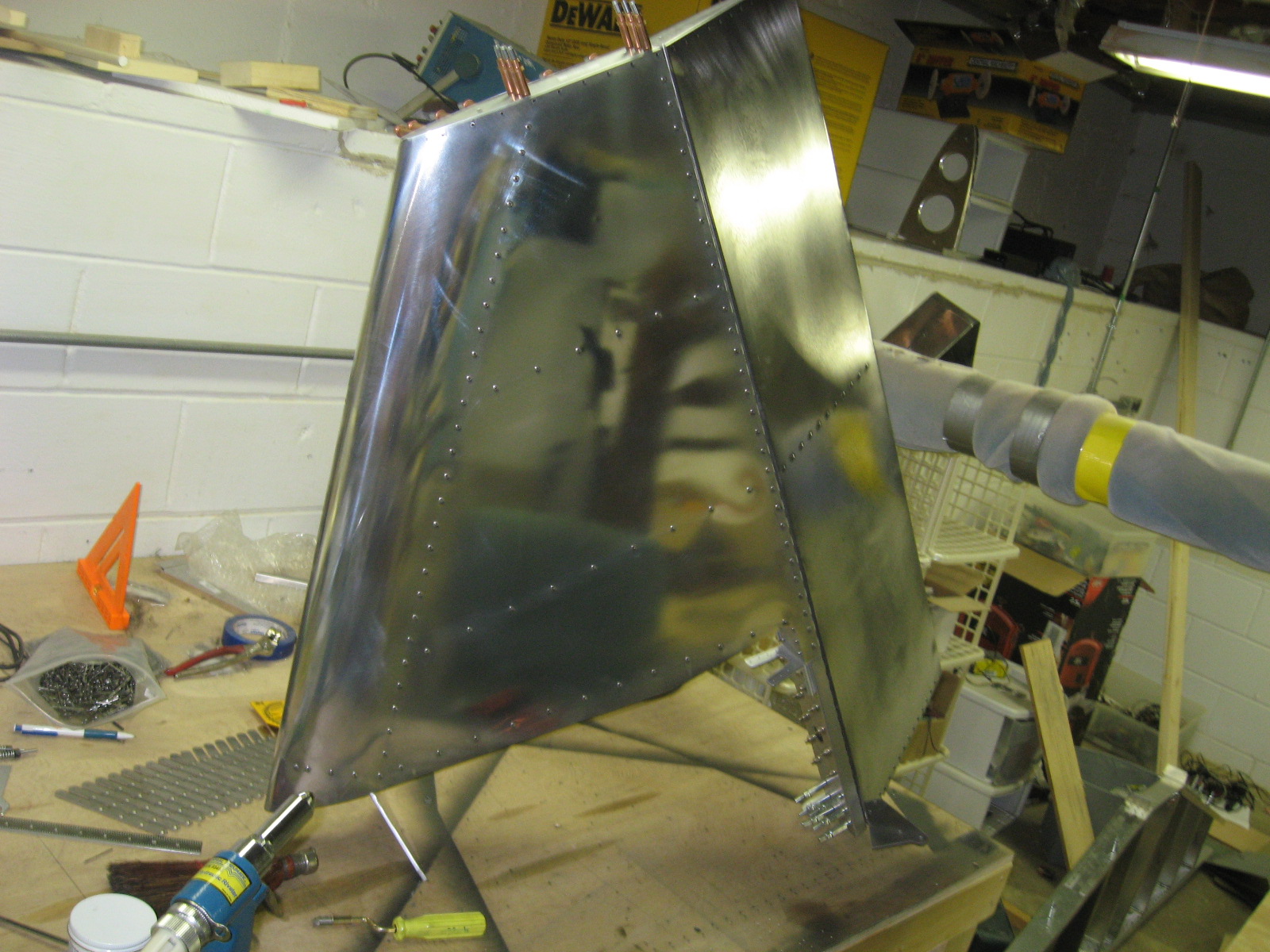
I riveted the skin to the vertical stabilizer and built the rudder.  I decided to polish the skins while I was at it.  They seem like they need some more work, but I’m pleased with the results so far.

Vertical Stabilizer Skin

I have attached the vertical stabilizer skin with clecos and drilled most of the holes to the final size.  I also attached the piano hinge for the rudder.  I need to disassemble and deburr, but should be ready to rivet it soon.

I noticed a laser cut part on the rear spar with edges that looked like they weren’t totally deburred.  It seemed like it would probably be fine–I couldn’t really catch my fingernail in any of the bumps, but I knew it would bother me.  I ended up drilling out the stainless steel rivets.  This was a huge chore with my HSS (high speed steel) bits.  Apparently I need to get some cobalt bits as they are good on stainless steel.  I don’t have enough rivets to finish the job and will need to order more of that type from Sonex.  Notice the empty holes.

First rivets

I decided to pull my first rivets.  I hand riveted the forward and rear tail spar and most of one elevator.

Here is the horizontal stabilizer from another angle.

Caroline was sympathetic about how much work pulling the rivets by hand was, so she let me get an air compressor!

The Harbor Freight air hydraulic riveter made quick work of the elevators and both are now almost complete.  I read the instruction manual for the riveter and was led to believe I needed to disassemble it and add oil.  Then the rivet gun didn’t work at all.   After searching the internet it seemed everyone who disregarded the instructions had no problem with the gun, but those who added oil had the same problem as me. Notice how the reviews on the Harbor Freight website are unusually hight–9 ratings for an average of 5/5 stars.  I bet these people didn’t disassemble it to add oil, or they just knew what they were doing :-)

While searching the internet for help, I found this amusing piece of advice about not adding oil.  Since this is a “hydraulic” riveter and not simply a pneumatic one, it is clear that oil is actually required in the riveter.  The trick is making sure you add it in the right place and not too much or too little or it won’t work correctly.  I now believe it comes ready to run right out of the box.

After spending 3 hours messing around and totally disassembling it, I realized I had added too much oil and was able to determine the correct amount.  I expect it to last the entire project now that I figured it out.  I operate it at ~45 psi and it is fantastic.  By tuning the pressure I can have the stem break off in one or two trigger pulls.  I prefer two.

Here I am demonstrating to Caroline how much harder the hand riveter is.  From the look on my face, it looks like I am right in the middle of the final stem-breaking squeeze.

Here are both of the mostly-completed elevators.
Aluminum Sheet Order

I thought it would be fun to try scratch building the fuselage.  Since I have already made all the aluminum angle components, I am thinking I might be able to have something beginning to resemble an airplane without too much effort.  We’ll see how well this idea holds.

Wicks seemed to have good prices on aluminum sheet, but said shipping for 5 sheets of 4’x12′ would be around $100.  I found a local company L. Miller & Son, Inc. with similar prices but no shipping charge.  I did end need to pay around $50 in taxes, but I would have needed to pay that on the other order anyway (Alabama wants you to provide proof you paid sales tax on the airplane).

I was concerned about getting 4’x12′ sheets to fit in the back of the van.  Everyone including myself seemed skeptical that they would roll, but they rolled easily and I used a ratcheting strap to keep them that way.  This is what 3 sheets of 4’x12′ .025″ and 2 sheets of .032″ look like rolled up in the back of a van.  It’s not nearly as impressive as it would be unrolled.

This would not work without the “Eagle Scouts” bumper sticker.